Calibration is defined in the international metrology dictionary as follows: "It is a series of operations that establish the relationship between the values displayed by measuring devices or measuring system under specified conditions, or the values represented by measurement or reference materials, and the corresponding values realized by the standards. TÜBİTAK SAGE Calibration Laboratory was established in 2004 to serve the calibration of devices within TÜBİTAK SAGE and was accredited by TÜRKAK in 2011 with the code AB-0085-K as a calibration laboratory within the scope of TSE EN ISO / IEC 17025 General Conditions Standard for the Competence of Experiment and Calibration Laboratories. Details of the accreditation scope of the laboratory can be accessed on the TÜRKAK website. TÜBİTAK SAGE Calibration Laboratory has set the goal of continuing its activities with technical excellence and high quality in accordance with current national and international standards in the relevant fields, whose effectiveness is constantly improved with the conditions of the TS EN ISO / IEC 17025 General Conditions for the Competence of Testing and Calibration Laboratories Standard. TÜBİTAK SAGE Calibration Laboratory aims to continue its activities with technical excellence and high quality in accordance with current national and international standards in the relevant fields, whose effectiveness is constantly improved by adhering to the TS EN ISO / IEC 17025 General Conditions Standard for the Competence of Experiment and Calibration Laboratories. Detailed information about the measurement capabilities of the TÜBİTAK SAGE Calibration laboratory is included.
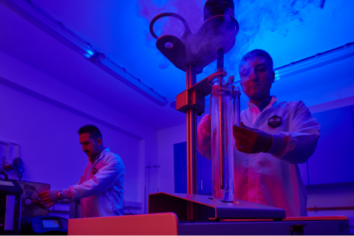
In temperature metrology, all measurements must be traceable to the International Temperature Scale 1990 (ITS-90). This scale is the most important element that ensures that all temperature measurements in the world are accurate, reliable and equivalent. The ITS-90 temperature scale has emerged with the development of many international temperature scales that have been used before. These scales were created to replace the 1968 International Temperature Scale, allowing temperature measurements to be made accurately and reproducibly and to be calculated most closely to the thermodynamic temperature corresponding to the measured temperature.
Comparative calibration of Numerical Indicator Thermometers, Thermocouples and Resistance Thermometers involving the temperature range from -90°C to 1100°C, based on the International Temperature Scale - 1990 (ITS-90) is carried out in the laboratory.
Uygulamalar:
Laboratuvarın verdiği hizmetler ve çalışma alanları aşağıda özetlenmiştir.
| Calibrated Products | Limit values |
|---|---|
| THERMOCOUPLES | Temperature Calibration -90 oC - 1100 oC |
| PLATINUM RESISTANCE THERMOMETER | Temperature Calibration -90 oC - 420 oC |
| DIGITAL THERMOMETER | Temperature Calibration -90 oC - 1100 oC |
| LIQUID GLASS THERMOMETER | Temperature Calibration -80 oC - 420 oC |
| DETERMINATION OF TEMPERATURE DISTRIBUTION IN TEMPERATURE CONTROLLED VOLUMES | Temperature Calibration -60 oC - 200 oC |
| DETECTION OF MOISTURE DISTRIBUTION IN TEMPERATURE CONTROLLED VOLUMES | Humidity Calibration 23 °C’de 20%RH - 95 %RH 30 °C’de 95%RH 60 °C’de 95%RH |
| ASH FURNACE | Temperature Calibration 250 oC - 1350 oC |
Hummidity measurements gain an increasing importance in production control with the studies carried out in the laboratory and industry in order to increase product quality, reduce costs, ensure human comfort and health. For example, moisture control applying in the cotton-based industry significantly affects the quality of cotton products. Humidity control in large markets or warehouses protects various metals from rusting and foodstuffs from spoiling. Humidity control, matter in terms of human health and comfort in the air conditioning of operating rooms, hospital rooms and incubators, meteorology measurements, automobile emission and air pollution measurements and ozone hole studies. In humidity measurements, relative humidity meters and dew-point temperature meters are often used to determine the amount of moisture in air or a gas.
Relative Humidity: Relative humidity is the ratio of partial water vapor pressure to saturated water vapor pressure in a closed volume and at the same temperature.
The relative humidity value depends on the temperature and pressure values of the air. As the temperature increases, the water vapor holding capacity of the air increases. The 100% relative humidity value means that the amount of water vapor that the air can hold is carried at full capacity. The air is saturated with water vapor. Condensation is observed when more water vapor is added to this state. Without changing the amount of moisture it contains, when the temperature value of the air at 100% relative humidity is increased, a decrease in the relative humidity value is observed. Condensation is observed when more water vapor is added to this state. Without changing the amount of moisture it contains, when the temperature value of the air at 100% relative humidity is increased, a decrease in the relative humidity value is observed.
Since the water vapor holding capacity of hot air is higher than that of cold air, a decrease in relative humidity is observed. A relative humidity of 50% indicates that the air carries half the amount of water vapor it can hold. The amount of water vapor in the air does not change as the temperature decreases. However, since the amount of water vapor at the low temperature air can carry is less, the relative humidity increases.
Humidity measurements are made in a very wide range of 109 when water vapor pressure is taken into account. Therefore, different sensors (sensors) and devices are required for this range. As a result, different moisture measuring devices and methods have emerged. The devices used in the calibration of numerical, mechanical and other relative humidity and temperature meters and dew-point temperature meters are given below:
- moisture sources
- dew-point temperature meter
- Relative humidity meter
A moisture source can be used as a reference. In this case the moisture source must be calibrated traceable to the national institute.
Applications:
The services and work areas provided by the laboratory are summarized below.
| Calibrated Products | Limit values |
|---|---|
| Temperature and Humidity Meter | 15 °C - 35 °C 20 %rh - 90 %rh |
Short description:
The creation of length standards and the realization of length measurements have a very important place in the development process of science and technology. In this process, the aim is to create nationally and internationally accepted length units by using primary level measurement systems and length standards with the requirements of technology and industry.
The creation of the unit of length and length measurements have been carried out in different ways in the past centuries. While in ancient times it was defined using the human body for units of length, a meter was first defined in 1791 as one in ten-million of the Earth's meridian passing through Paris. Later, adhering to this definition, a 1-meter bar was produced and used from Platinum material. However, considering that the lengths of these metal prototypes (in a sense, gauge blocks) may change over time, it is thought that the unit of length should be an unchanging quantity, as in other SI units. “1 meter is the distance traveled by light in vacuum in a time interval of 1/299 792 458 seconds.” The main fields of study of length and dimensional metrology are: Frequency stable lasers and frequency measurements, gauge blocks and interferometric measurements, angle measurements, surface roughness measurements, nanometrology, diameter and form (geometric) measurements, long distance measurements, industrial measurements and optical tooling, and three-dimensional ( CMM metrology) measurements.
Basic measuring devices are dimensional measuring devices that are widely used in industry. Thousands of them are actively used in some factories.
They are widely used in the control of whether the manufactured part is within the production tolerances at the time of manufacture or after manufacturing in the first control of the manufactured part before starting precise measurements.
The devices defined as basic measuring devices can be gathered under four headings;
- Micrometer
- Calliper
- Vernier calliper
- Measuring Clock
Applications:
| # | Calibrated Products | Limit values |
|---|---|---|
| 1 | Micrometer | 0 ≤ L ≤ 300 mm (Division Value: 0.001 mm) 300 ≤ L≤ 500 mm (Division Value: 0.01 mm) |
| 2 | Calliper | 0 ≤ L ≤ 1000 mm (Division Value: 0.01 mm /0.02 mm /0.05 mm) |
| 3 | Measuring Clock | 0 ≤ L ≤ 100 mm (Division Value: 0.001 mm) |
| 4 | Vernier calliper | 0 ≤ L ≤ 1000 mm (Division Value: 0.01 mm /0.02 mm /0.05 mm) |
Short description:
Nowadays, precise mass measurements are required for many areas. Weighting Instruments are used to measure mass in chemistry, health, environment, scientific studies and commerce. Calibration of Weighting Instruments is carried out with international mass standards traceable to the prototype of the kilogram. High-precision mass standards are maintained in national metrology institutes.
A weighing device is a measuring device used to determine the mass of an object by taking advantage of the gravitational effect on it.
Non-automatic weighing devices are often used to quantify a load as mass. The purpose of the calibration is the indication given by the instrument in response to an applied load. Results are expressed in units of mass.
A weighing device is classified as automatic and non-automatic weighing device according to its method of operation. A non-automatic weighing device is a device that requires an operator's intervention in placing the load on the load carrier, lifting it and obtaining the weighing results.
Applications:
| Calibrated Products | Limit values |
| Weighting Instruments | 1 mg ≤ m ≤ 20 kg (with E2 class weights) 10 kg ≤m ≤ 50 kg (with F1 class weights) 10 kg ≤m ≤ 100 kg (with F2 class weights) 5 kg ≤ m≤ 200 kg (with M1 class weights) |
Short description:
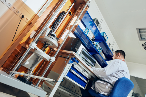
Since the force measurement magnitude is a derived quantity, or in other words, it is possible to measure not directly itself, but other magnitudes related to it, so far, human beings have developed various methods in force measurement. These are balancing with a known load with a rough grouping, taking advantage of the deformation caused by the effect of force on a flexible body, and changing some physical properties of the materials under the effect of force.
As is known, material testing machines are used to determine the mechanical properties of materials. Mechanical properties are determined based on the force and elongation values measured by the testing machine. Checking the accuracy of these two parameters in the calibration of material testing machines will ensure the measurement results.
Applications:
| Calibrated Products | Limit values |
|---|---|
| FORCE MEASUREMENT SYSTEMS | 20 N ≤ F≤ 100 kN (Tension with 0.5 class load cell) 20 N ≤ F≤ 1000 kN (Compression with 0.5 class loadcell) |
Short description:
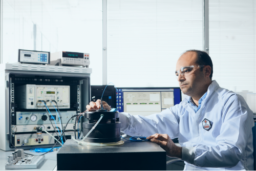
The commonly used measurement magnitude in vibration measurements is acceleration. The unit of acceleration magnitude is defined in the International System of Units (SI) as the unit derived using the basic quantities, meters (m) and seconds (s). Therefore, unlike the basic SI units, it does not have a declared definition by the CIPM.
The primary standard in the field of vibration is obtained by the calibration of accelerometers, which are reference standards. In the calibration, the complex sensitivity value of the accelerometer is determined. The sensitivity of the vibration transducer; It is defined as the ratio of electrical output to applied mechanical input. Sensitivity can be measured independently at each frequency within the operating frequency range of the accelerometer. Sensitivity for all transducers varies with frequency. If the sensitivity is independent of the frequency in a certain frequency region, it is called the calibration factor for that region.
The reference accelerometer and the accelerometer, whose sensitivity will be determined, are connected back to back and exposed to the same acceleration level. Since the acceleration value of both accelerometers is the same, the output ratio of the accelerometers is equal to the ratio of their sensitivities.
Vref/Sref= Vx/Sx
Vref, Vx: Voltages of reference and accelerometer to be calibrated
Sref, Sx: The reference and sensitivity value of the accelerometer to be calibrated
In vibration measurements made in the field, the measurement system should be checked using portable vibration exciters before and after the measurement. The vibrator is a vibration source that generates an acceleration of 10.0 m/s2 at a nominal frequency of 159.2 Hz. The nominal characteristics of vibration exciters are defined in the ISO 8041 standard. The important parameters are the produced acceleration value, the total harmonic distortion of the acceleration and the frequency of the vibration.
The level of acceleration produced by the vibration exciter is equal to the ratio of the sensitivity of the accelerometer to the voltage produced by the vibrating surface-mounted accelerometer and the conditioner (load or voltage) amplifier. The acceleration produced by the vibration exciter can be calculated from the values.
a=V/Sqa*k
V : Output voltage of accelerometer-load amplifier
Sqa : Accelerometer's load sensitivity
k : Conversion coefficient
Applications:
| Calibrated Products | Limit values |
|---|---|
| Accelerometer (Load Sensitivity) | 0.98 m/s2≤acceleration≤98 m/s2 (10 Hz - 10 kHz) |
| Accelerometer (Voltage Sensitivity) | 0.98 m/s2≤acceleration≤98 m/s2 (10 Hz - 10 kHz) |
| Shock accelerometer | 196 m/s2≤acceleration≤98.000 m/s2 |
| Vibration exciter | 0.98 m/s2 (160 Hz) |
Short description:
Pressure is defined as the vertical force acting on a unit area or the stress at any point in a fluid in a closed container. Pressure is theoretically defined by the formula p=F/A. Here, A is the unit area and F is the force. Pressure measurements are performed in five different ways according to the reference point. These can be classified as follows;
- Gauge (Relative) Pressure
- Absolute Pressure
- Negative Pressure
- Differential Pressure
- Atmospheric pressure
To briefly explain these measurements:
- Gauge (relative) pressure measurement: Pressure measurement made by taking the atmospheric pressure as reference.
- Absolute pressure measurement: A measurement made by taking (absolute) vacuum as reference.
- Negative gage pressure measurement: Pressure measurement under atmospheric pressure with taking atmospheric pressure as a reference.
- Differential pressure measurement: It is the pressure measurement made between two unknown pressures.
- Atmospheric pressure measurement: Measurement of ambient air pressure with (absolute) vacuum as a reference.
Dynamic Pressure Calibration:
In the rapidly changing and developing industrial and scientific studies, static pressure measurements for some application areas cannot provide fully satisfactory information about the system. It is necessary to reveal the dynamically change and behavior of the pressure in the system in very small time units. For this purpose, dynamic pressure transducers, amplifiers and indicators that can dynamically measure the pressure in the system have been produced in the field of dynamic pressure metrology that has emerged.
At the same time, studies have been carried out to ensure their traceability by dynamically calibrating the dynamic pressure transducers and other components used together.
- What is dynamic pressure?
In a measurement made, if the measured physical quantity changes over time and this change is of significant importance in terms of the measurement result; we can define this measurement as a dynamic measurement.
In some such measurements, only the maximum, that is, the peak value of the measurement, is important, while in some measurements, the variation of the measurement over time or the values it takes within a certain time interval may be important.
Today, many types of sensors are used in industry to measure physical parameters such as pressure, force, torque, temperature and vibration. Therefore, it can be said that sensors with different structures, different types and different operating characteristics are used for different disciplines and measurement characteristics. As a result of the dynamic properties of the sensors, there are great differences between different types of sensors. Here are some different types of sensors used in dynamic pressure measurement applications:
- Semiconductor piezoresistive sensors,
- Piezoelectric sensors,
- Strain gauges,
- Microelectromechanical systems (MEMS)
Dynamic pressure calibration can be done by abruptly lowering the pressure from the known static reference pressure value using quick-opening valves. Or the hydraulic impulse comparison method can be used using a transfer standard. Another method in this regard is the use of shock tubes. Depending on the calibrator type and pressure environment used, the desired pressure can be reached in milliseconds or microseconds.
In the laboratory, comparative calibration of pressure measuring instruments is performed statically between -0.9 bar and 1000 bar, and dynamically between 0 and 5000 bar.
Applications:
| Calibrated Products | Limit values |
|---|---|
| Relative Pressure Analogue and Digital Display Manometers, Pressure Calibrator, Pressure Transducer, Pressure Transmitter, Differential Pressure Meter | -0,95≤ p ≤ 0 bar 0,7≤ p ≤ 35 bar 35< p ≤ 140 bar 1≤ p ≤ 200 bar 200< p ≤ 1000 bar |
| Absolute Pressure Analogue and Digital Display Manometers, Pressure Calibrator, Pressure Transducer, Pressure Transmitter, Differential Pressure Meter | -0,95≤ p ≤ 0 bar 0,7≤ p ≤ 35 bar 35< p ≤ 140 bar 1≤ p ≤ 200 bar 200< p ≤ 1000 bar |
| Dynamic Pressure Gauge | 20< p ≤ 5000 bar |
Short description:
The basis of electrical units is AMPER. However, Voltage and Resistance references are used for the enclosure of electrical units. For a long time, Weston cells were used as voltage references. These cells produce 1.0186 V voltage according to electrochemical principles. This voltage is highly sensitive to ambient temperature. This can cause some problems. In addition, the loading capacity of these elements is low.
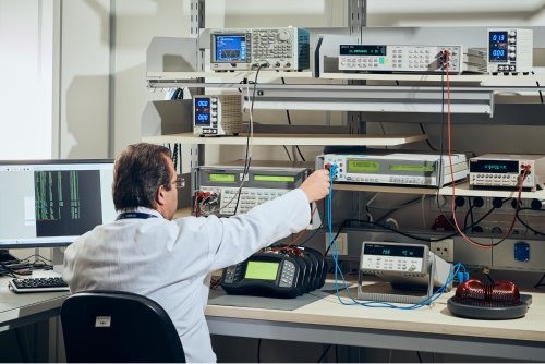
Resistors produced from special conductors (Manganin, Zeranin, etc.) have been used as a resistance reference for a long time. The temperature sensitivity of these structures is quite low and their time-dependent deviations are sufficiently low. Their structural forms are designed to be affected by environmental influences as little as possible. In order to eliminate the slight deviations in the values of the reference resistors, these resistors are kept as a group in national institutes and the group is used as the "basic reference".
In order to harmonize electrical and mechanical units, the "absolute" unit system was adopted, but in the following years, many different unit systems emerged. In order to eliminate this confusion and provide unity in the international arena, the "International System of Units" (SI-International System of Units) was accepted in 1960.
Applications:
| Calibrated Products | Limit values |
|---|---|
| Analog Multimetre Dijital Multimetre Pens Multimetre | DC/AC CURRENT Measurement and Application: 20 A DC/AC VOLTAGE Measurement and Application: 1000V Resistance Measurement: 20 GΩ Resistance Application : 300 MΩ |
| Data collecting | DC/AC CURRENT Measurement and Application: 20 A DC/AC VOLTAGE Measurement and Application: 1000V Resistance Measurement: 20 GΩ Resistance Application : 300 MΩ |
| Power source | 20A/1000V |
| Oscilloscope | Up to 1 GHz |
| Signal Conditioner | GAIN Detection of DC/ICP/Charge/IEPE Type Signal Conditioner |
RESOURCES;
TÜBİTAK UME METROLOGY BOOK
VII. NATIONAL MEASUREMENT SCIENCE CONGRESS - Calibration Methods of Dynamic Pressure Transducers - Yasin DURGUT,İlknur KOÇAŞ